Next: Flaws in the warped Up: 7.4 Improving Latency and Previous: The power of prediction Contents Index
Due to both latency and imperfections in the prediction process, a last-moment adjustment might be needed before the frame is scanned out to the display. This is called post-rendering image warp [203] (it has also been rediscovered and called time warp and asynchronous reprojection in the recent VR industry). At this stage, there is no time to perform complicated shading operations; therefore, a simple transformation is made to the image.
 |
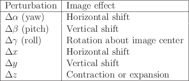
Suppose that an image has been rasterized for a particular viewpoint, expressed by position ![]() and orientation given by yaw, pitch, and roll
and orientation given by yaw, pitch, and roll
![]() . What would be different about the image if it were rasterized for a nearby viewpoint? Based on the degrees of freedom for viewpoints, there are six types of adjustments; see Figure 7.19. Each one of these has a direction that is not specified in the figure. For example, if
. What would be different about the image if it were rasterized for a nearby viewpoint? Based on the degrees of freedom for viewpoints, there are six types of adjustments; see Figure 7.19. Each one of these has a direction that is not specified in the figure. For example, if
![]() is positive, which corresponds to a small, counterclockwise yaw of the viewpoint, then the image is shifted horizontally to the right.
is positive, which corresponds to a small, counterclockwise yaw of the viewpoint, then the image is shifted horizontally to the right.
 |
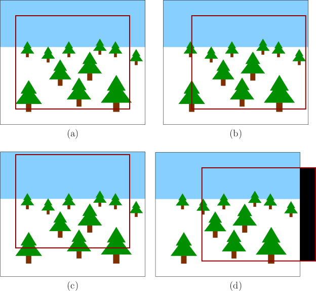
Figure 7.20 shows some examples of the image warp. Most cases require the rendered image to be larger than the targeted display; otherwise, there will be no data to shift into the warped image; see Figure 7.20(d). If this ever happens, then it is perhaps best to repeat pixels from the rendered image edge, rather than turning them black [203].
Steven M LaValle 2020-01-06