
Next: The power of visibility Up: 9.3 Tracking Position and Previous: Why not just integrate Contents Index
The IMU-based approach to tracking was passive in the sense that it relied on sources of information that already exist in the environment. Instead, an active approach can be taken by transmitting waves into the environment. Since humans operate in the same environment, waves that are perceptible, such as light and sound, are not preferred. Instead, common energy sources in active tracking systems include infrared, ultrasound, and electromagnetic fields.
Consider transmitting an ultrasound pulse (above ![]() Hz) from a speaker and using a microphone to listen for its arrival. This is an example of an emitter-detector pair: The speaker is the emitter, and the microphone is the detector. If time measurement is synchronized between source and destination, then the time of arrival (TOA or time of flight) can be calculated. This is the time that it took for the pulse to travel the distance
Hz) from a speaker and using a microphone to listen for its arrival. This is an example of an emitter-detector pair: The speaker is the emitter, and the microphone is the detector. If time measurement is synchronized between source and destination, then the time of arrival (TOA or time of flight) can be calculated. This is the time that it took for the pulse to travel the distance ![]() between the emitter and detector. Based on the known propagation speed in the medium (
between the emitter and detector. Based on the known propagation speed in the medium (![]() m/s for ultrasound), the distance
m/s for ultrasound), the distance ![]() is estimated. One frustrating limitation of ultrasound systems is reverberation between surfaces, causing the pulse to be received multiple times at each detector.
is estimated. One frustrating limitation of ultrasound systems is reverberation between surfaces, causing the pulse to be received multiple times at each detector.
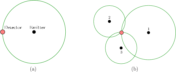 |
When functioning correctly, the position of the detector could then be narrowed down to a sphere of radius ![]() , centered at the transmitter; see Figure 9.9(a). By using two transmitters and one microphone, the position is narrowed down to the intersection of two spheres, resulting in a circle (assuming the transmitter locations are known). With three transmitters, the position is narrowed down to two points, and with four or more transmitters, the position is uniquely determined.9.1 The emitter and detector roles could easily be reversed so that the object being tracked carries the emitter, and several receivers are placed around it. The method of combining these measurements to determine position is called trilateration. If electromagnetic waves, such as radio, light, or infrared, are used instead of ultrasound, then trilateration could still be applied even though the impossible to measure the propagation time directly. If the transmitter amplitude is known then distance can be estimated based on power degradation, rather than TOA. Alternatively, a time-varying signal can be emitted and its reflected phase shift can be estimated when the received signal is superimposed onto the transmitted signal.
, centered at the transmitter; see Figure 9.9(a). By using two transmitters and one microphone, the position is narrowed down to the intersection of two spheres, resulting in a circle (assuming the transmitter locations are known). With three transmitters, the position is narrowed down to two points, and with four or more transmitters, the position is uniquely determined.9.1 The emitter and detector roles could easily be reversed so that the object being tracked carries the emitter, and several receivers are placed around it. The method of combining these measurements to determine position is called trilateration. If electromagnetic waves, such as radio, light, or infrared, are used instead of ultrasound, then trilateration could still be applied even though the impossible to measure the propagation time directly. If the transmitter amplitude is known then distance can be estimated based on power degradation, rather than TOA. Alternatively, a time-varying signal can be emitted and its reflected phase shift can be estimated when the received signal is superimposed onto the transmitted signal.
If the detectors do not know the precise time that the pulse started, then they could compare differences in arrival times between themselves; this is called time difference of arrival (TDOA). The set of possible locations is a hyperboloid instead of a sphere. Nevertheless, the hyperboloid sheets can be intersected for multiple emitter-detector pairs to obtain the method of multilateration. This was used in the Decca Navigation System in World War II to locate ships and aircraft. This principle is also used by our ears to localize the source of sounds, which will be covered in Section 11.3.
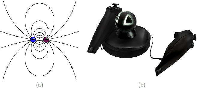 |
Finally, some methods could track position by emitting a complicated field that varies over the tracking area. For example, by creating a magnetic dipole, perhaps coded with a signal to distinguish it from background fields, the position and orientation of a body in the field could be estimated in the field; see Figure 9.10(a). This principle was used for video games in the Razer Hydra tracking system in a base station that generated a magnetic field; see Figure 9.10(b). One drawback is that the field may become unpredictably warped in each environment, causing straight-line motions to be estimated as curved. Note that the requirements are the opposite of what was needed to use a magnetometer for yaw correction in Section 9.2; in that setting the field needed to be constant over the tracking area. For estimating position, the field should vary greatly across different locations.