Next: Constraints and inverse kinematics Up: 9.4 Tracking Attached Bodies Previous: Eye tracking Contents Index
Suppose that an eye tracking method has estimated the eye orientation relative to the human skull and it needs to be placed accordingly in the virtual world. This transformation must involve a combination of the head and eye transforms. For a more complicated problem, consider placing the right index finger in the world by using pose of the torso along with all of the angles formed between bones at each joint. To understand how these and other related problems are solved, it is helpful to first consider 2D examples.
 |
Each body of a multibody system is called a link, and a pair of bodies are attached at a joint, which allows one or more DOFs of motion between them. Figure 9.19 shows two common ways that one planar body might move while attached to another. The revolute joint is most common and characterizes the motion allowed by a human elbow.
 |
Consider defining a chain of ![]() links,
links, ![]() to
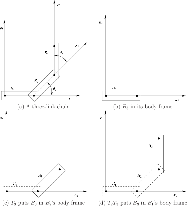
to ![]() , and determining the location of a point on the last link. The points on each link are defined using coordinates of its own body frame. In this frame, the body appears as shown for
, and determining the location of a point on the last link. The points on each link are defined using coordinates of its own body frame. In this frame, the body appears as shown for ![]() in Figure 9.20, with the origin at the joint that connects
in Figure 9.20, with the origin at the joint that connects ![]() to
to ![]() and the
and the ![]() axis pointing through the joint that connects
axis pointing through the joint that connects ![]() to
to ![]() . To move the points on
. To move the points on ![]() to the proper location in the body frame of
to the proper location in the body frame of ![]() , the homogeneous transform
, the homogeneous transform
Points on ![]() are moved into the body frame for
are moved into the body frame for ![]() by applying the product
by applying the product
![]() . A three-link example is shown in Figure 9.21. To move the first link
. A three-link example is shown in Figure 9.21. To move the first link ![]() into the world frame, a general 2D homogeneous transform can be applied:
into the world frame, a general 2D homogeneous transform can be applied:
A chain of 3D links is handled in the same way conceptually, but the algebra becomes more complicated. See Section 3.3 of [165] for more details. Figure 9.22 shows six different kinds of joints that are obtained by allowing a pair of 3D links to slide against each other. Each link is assigned a convenient coordinate frame based on the joints. Each homogeneous transform ![]() contains a mixture of constants and variables in which the variables correspond to the freedom allowed by the joint. The most common assignment scheme is called Denavit-Hartenberg parameters [111]. In some settings, it might be preferable to replace each
contains a mixture of constants and variables in which the variables correspond to the freedom allowed by the joint. The most common assignment scheme is called Denavit-Hartenberg parameters [111]. In some settings, it might be preferable to replace each ![]() by a parameterized quaternion that rotates the body, followed by a simple addition that translates the body.
by a parameterized quaternion that rotates the body, followed by a simple addition that translates the body.
A tree of links may also be considered; a common example is a human torso serving as the root, with a head, two arms, and two legs being chains that extend from it. The human hand is another example. Coordinate frames in this case are often assigned using Kleinfinger-Khalil parameters [150].
Steven M LaValle 2020-01-06