Jun Qu
See more examples in Example section.
See more examples in Example section.
In this project, we consider mobile robots(car-like and car-trailer robots). The main task is to develop and implement a path planning system that is used to being a mobile robot from an initial configuration to a goal configuration. Given a complicated geometric model for the world, a continuous, collision-free path will be computed out. By using RRT, an efficient planner was designed and some local improvement of RRT was developed. Many examples were tested and the results were pretty good.
The mobile robots are known to be nonholonomic, i.e..,
they are subject to nonintegrable equality nonholonomic constraints involving
the velocity. In other words, the dimension of the admissible velocity
space is smaller than the dimension of the configuration space. In addition,
the range of possible controls is usually further constrained by inequality
constraints due to mechanical stops in steering mechanism of the tractor.
Car-like:
C = R2*S1Car-Trailer:
q (x, y, theta)-dx*sin(theta)+dy*cos(theta) = 0
dx = v*cos(fi)*cos(theta)
dy = v*cos(fi)*sin(theta)
dtheta = (v/L)*sin(fi)v=[-1, 1]
|fi| <= MAXfidistance (p, q) = [(p.x-q.x)^2 + (p.y-q.y)^2 + A*min((p.theta-q.theta)^2 + (p.theta-q.theta+2*PI)^2 + (p.theta-q.theta-2*PI)^2) ] ^0.5
C = R2*S1*S1where, 0 < MAXfi < PI/2 . In this project, I tried MAXfi = PI/4 and PI/3.
q (x, y, theta1, theta2)-dx*sin(theta1)+dy*cos(theta1) = 0
-dx*sin(theta2)+dy*cos(theta2)-L2*dtheta2 = 0dx = v*cos(fi)*cos(theta1)
dy = v*cos(fi)*sin(theta1)
dtheta1 = (v/L1)*sin(fi)
dtheta2 = (v/L2)*cos(fi)*sin(theta1-theta2)v=[-1, 1]
|fi| <= MAXfidistance (p, q) = [(p.x-q.x)^2 + (p.y-q.y)^2 + A1*min((p.theta1-q.theta1)^2 + (p.theta1-q.theta1+2*PI)^2 + (p.theta1-q.theta1-2*PI)^2) + A2*min((p.theta2-q.theta2)^2 + (p.theta2-q.theta2+2*PI)^2 + (p.theta2-q.theta2-2*PI)^2) ] ^0.5
dx = v*cos(theta)In the former expression, the velocity, v, is the velocity of the front wheels. In later expression. the velocity, v, is the velocity of the rear wheels. The former one can have larger range of fi, and the translation has relationship with rotation, which makes sense. Also because the real cars are front wheel driving, the former one is more reasonable. So I chose the former expression in my project.
dy = v*sin(theta)
dtheta = (v/L)*tan(fi)
RRT, Rapid-Exploring Random Trees, is suited for both holonomic and nonholonomic path planning problem. It is efficient and robust, especially designed to handle nonholonomic constrains and high degree of freedom. In this project, RRT is the main weapon. In order to fit my problems, some modification of the standard RRT algorithm was made. So I list the modified part here.
d = infinity
r = infinity
while ( d > tolerance ){
for i=0 to M {return Gq = Goal_Region_Biased_Conf (qGoal, PG, r)vn = Nearest_Vertex (qGoal, G)
vn = Nearest_Vertex (q, G)
input = Optm_Input (vn, q, obsts)
qn = New_conf (vn, input)
}
d = distance (qGoal, vn)
r = k*d
}
}
In general, for holonomic, Rand_Conf() or Goal_Biased_Conf() are used to get the randomized configurations. However, in nonholonomic problems, such as car-like, it doesn't well enough. Many times it takes long time to get to the Goal with high accuracy. For example, 0<x<100, 0<y<100, and 0<=theta<2*PI, it is hard to get to qGoal as close as d<2.
After trying several ways, I designed a new version of the randomized configuration algorithm, Goal_Region_Biased_Conf(). This function gives the Goal region more probability to have new nodes, which makes it faster to get to the Goal. Note: the Goal region keeps changing to be smaller and smaller. So the RRT has both global and local properties: it can get to anywhere in global and have more details in Goal region. Using Goal_Region_Biased_Conf(), the Goal can be get much faster with high accuracy. For the same example, the Goal can be reached as close as d<0.5.
Goal_Region_Biased_Conf (qGoal, PG, r){See the following RRT, which is the RRT of Example(6). Obviously, the Goal region has more sampled configuration, which makes the tree get to the Goal faster with high accuracy.PG2 = 0.5
R >> x;
if (x< PG)
return (goal);
else if (x< PG2){
q = Rand_Conf();
while (distance (q, qGoal) > r)
q=Rand_Conf();
return(q);
}
else return(Rand_Conf());
}
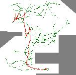
RRT of Example (6)
(2) Optm_Input()
Optm_Input (vn, q, obsts){Because it is a nonholonomic problem, after finding the nearest node (vn) of the randomized configuration (q), we have to find the optimal input(v, fi) to get the new node (qn) closest to q. This is a optimization problem, defined as following:u = Optimazition(vn, q)
if u.fi > MAXfi
u.fi = MAXfi
else if u.fi < -MAXfi
u.fi = -MAXfiu1.fi = u.fi
u2.fi = u.fi
while (Collision (u1, obsts)){
u1.fi = u1.fi + small_angle
}
qn1 = New_Conf(vn, u1);
d1 = distance(qn1, q)
while (Collision (u2, obsts)){
u2.fi = u2.fi - small_angle
}
qn2 = New_Conf(vn, u2);
d2 = distance(qn2, q)optm_u = (d1<d2)? u1:u2
return (optm_u)
}
[distance(qn, q)]^2 = (qn.x-q.x)^2 + (qn.y-q.y)^2 + A*min[(qn.theta-q.theta), (qn.theta-q.theta+2*PI), (qn.theta-q.theta-2*PI)]^2 --------------------- (1)Car-Trailer:
where,
qn.x = vn.x + v*dt*cos(fi)*sin(vn.theta)
qn.y = vn.y + v*dt*cos(fi)*cos(vn.theta)
qn.theta = vn.theta + v*dt*sin(fi)if v = 1, do the first derivative of (1) for fi, and make it equal to zero.
d([distance(qn, q)]^2)/d(fi) = a*cos(fi) + b*sin(fi) + c*cos(fi)*sin(fi) = 0 ---(2)if v = -1,d([distance(qn, q)]^2)/d(fi) = a*cos(fi) + b*sin(fi) - c*cos(fi)*sin(fi) = 0 ---(3)wherea = (A/L)*min[(qn.theta-q.theta), (qn.theta-q.theta+2*PI), (qn.theta-q.theta-2*PI)]Equations (2)(3) can be deduced to degree four polynomial equations, which have close form roots. As a special case, when A = L*L, c = 0, the root can be got immediately: fi = atan(a/b).
b = (vn.x-q.x)*cos(vn.theta) + (vn.y-q.y)*sin(vn.theta))
c = A/(L*L)-1By comparing the two optimal input(v=-1, fi=optimal_fi_1) and input(v=1, fi=optimal_fi_2), the optimal input of vn is obtained. Then qn can be computed.
By the same proach, we have:
if v = 1, do the first derivative of (1) for fi, and make it equal to zero.
NOTE: Collision detection must be included in Optm_Input(). That means the optimal input may not be implemented, because of collision. When collision happens, new inputs should be tried. Among the collision free inputs, the one which is closest to the optimal input is the best one. In this project, the incremental collision detection algorithm is used.d([distance(qn, q)]^2)/d(fi) = g*cos(fi) + h*sin(fi) + m*cos(fi)*sin(fi) = 0 --(4)if v = -1,d([distance(qn, q)]^2)/d(fi) = g*cos(fi) + h*sin(fi) - m*cos(fi)*sin(fi) = 0 --(5)whereg = (A1/L1)*min[(qn.theta1-q.theta1), (qn.theta1-q.theta1+2*PI), (qn.theta1-q.theta1-2*PI)]Equations (4)(5) can be deduced to degree four polynomial equations, which have close form roots. So until now we have solved the optmazition problem.
h = (vn.x-q.x)*cos(vn.theta1)+(vn.y-q.y)*sin(vn.theta1))
m =[ -1 + A1/(L1*L1) - A2/(L2*L2)*(sin(vn.theta1-vn.theta2))^2 ]*dt
In this project, we have used RRT as the nonholonomic path planning algorithm. By introducing Goal_Region_Biased_Conf(), and Optm_Input(), the planner works very well(fast and accurately) for car-like and car-trailer nonholonomic system. (see examples)
Although the planner works well now, there are some problems left: