Next: A polyhedral C-space obstacle Up: 4.3.2 Explicitly Modeling : Previous: A polygonal C-space obstacle
So far, the method quickly identifies each edge that contributes to
![]() . It can also construct a solid representation of
. It can also construct a solid representation of
![]() in
terms of half-planes. This requires defining
in
terms of half-planes. This requires defining ![]() linear equations
(assuming there are no collinear edges).
linear equations
(assuming there are no collinear edges).
 |
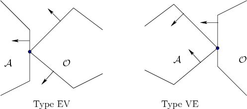
There are two different ways in which an edge of
![]() is generated,
as shown in Figure 4.16 [282,657]. Type
EV contact refers to the case in which an edge
of
is generated,
as shown in Figure 4.16 [282,657]. Type
EV contact refers to the case in which an edge
of ![]() is in contact with a vertex of
is in contact with a vertex of ![]() . Type EV contacts
contribute to
. Type EV contacts
contribute to ![]() edges of
edges of
![]() , once for each edge of
, once for each edge of ![]() . Type VE contact refers to the case in which a
vertex of
. Type VE contact refers to the case in which a
vertex of ![]() is in contact with an edge of
is in contact with an edge of ![]() . This contributes to
. This contributes to
![]() edges of
edges of
![]() . The relationships between the edge normals are
also shown in Figure 4.16. For Type EV, the inward edge
normal points between the outward edge normals of the obstacle edges
that share the contact vertex. Likewise for Type VE, the outward edge
normal of
. The relationships between the edge normals are
also shown in Figure 4.16. For Type EV, the inward edge
normal points between the outward edge normals of the obstacle edges
that share the contact vertex. Likewise for Type VE, the outward edge
normal of ![]() points between the inward edge normals of
points between the inward edge normals of ![]() .
.
Using the ordering shown in Figure 4.15b, Type EV
contacts occur precisely when an edge normal of ![]() is encountered,
and Type VE contacts occur when an edge normal of
is encountered,
and Type VE contacts occur when an edge normal of ![]() is encountered.
The task is to determine the line equation for each occurrence.
Consider the case of a Type EV contact; the Type VE contact can be
handled in a similar manner. In addition to the constraint on the
directions of the edge normals, the contact vertex of
is encountered.
The task is to determine the line equation for each occurrence.
Consider the case of a Type EV contact; the Type VE contact can be
handled in a similar manner. In addition to the constraint on the
directions of the edge normals, the contact vertex of ![]() must lie on
the contact edge of
must lie on
the contact edge of ![]() . Recall that convex obstacles were
constructed by the intersection of half-planes. Each edge of
. Recall that convex obstacles were
constructed by the intersection of half-planes. Each edge of
![]() can be defined in terms of a supporting half-plane; hence, it is only
necessary to determine whether the vertex of
can be defined in terms of a supporting half-plane; hence, it is only
necessary to determine whether the vertex of ![]() lies on the line
through the contact edge of
lies on the line
through the contact edge of ![]() . This condition occurs precisely as
. This condition occurs precisely as
![]() and
and ![]() are perpendicular, as shown in Figure 4.17,
and yields the constraint
are perpendicular, as shown in Figure 4.17,
and yields the constraint
![]() .
.
Note that the normal vector ![]() does not depend on the configuration
of
does not depend on the configuration
of ![]() because the robot cannot rotate. The vector
because the robot cannot rotate. The vector ![]() , however,
depends on the translation
, however,
depends on the translation
![]() of the point
of the point ![]() .
Therefore, it is more appropriate to write the condition as
.
Therefore, it is more appropriate to write the condition as
![]() . The transformation equations are linear for
translation; hence,
. The transformation equations are linear for
translation; hence,
![]() is the equation of a line
in
is the equation of a line
in ![]() . For example, if the coordinates of
. For example, if the coordinates of ![]() are
are ![]() for
for
![]() , then the expression for
, then the expression for ![]() at configuration
at configuration ![]() is
is
![]() . Let
. Let
![]() . Let
. Let
![]() . Observe that any
configurations not in
. Observe that any
configurations not in ![]() must lie in
must lie in
![]() . The half-plane
. The half-plane ![]() is
used to define one edge of
is
used to define one edge of
![]() . The obstacle region
. The obstacle region
![]() can
be completely characterized by intersecting the resulting half-planes
for each of the Type EV and Type VE
contacts. This yields a convex polygon in
can
be completely characterized by intersecting the resulting half-planes
for each of the Type EV and Type VE
contacts. This yields a convex polygon in ![]() that has
that has ![]() sides, as expected.
sides, as expected.
 |
Steven M LaValle 2012-04-20