The manipulation planning problem generally can be solved by forming a
manipulation graph,
 [16,17]. Let a
connected component of
  refer to any connected component
of
 that is lifted into the state space by ignoring the mode.
There are two copies of the connected component of
 , one for
each mode. For each connected component of
  , a vertex exists
in
 . An edge is defined for each transfer path or transit
path that connects two connected components of
  . The general
approach to manipulation planning then is as follows:
- Compute the connected components of
 to yield the
vertices of
 .
.
- Compute the edges of
 by applying ordinary motion planning
methods to each pair of vertices of
 .
.
- Apply motion planning methods to connect the initial and goal
states to every possible vertex of
 that can be reached without
a mode transition.
- Search
 for a path that connects the initial and goal
states. If one exists, then extract the corresponding solution as a
sequence of transit and transfer paths (this yields
  , the
actions that cause the required mode changes).
This can be considered as an example of hierarchical planning,
as described in Section 1.4.
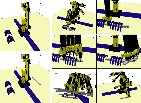
Figure 7.17:
This example was solved in [244]
using the manipulation planning framework and the visibility-based
roadmap planner. It is very challenging because the same part must be
regrasped in many places.
 |
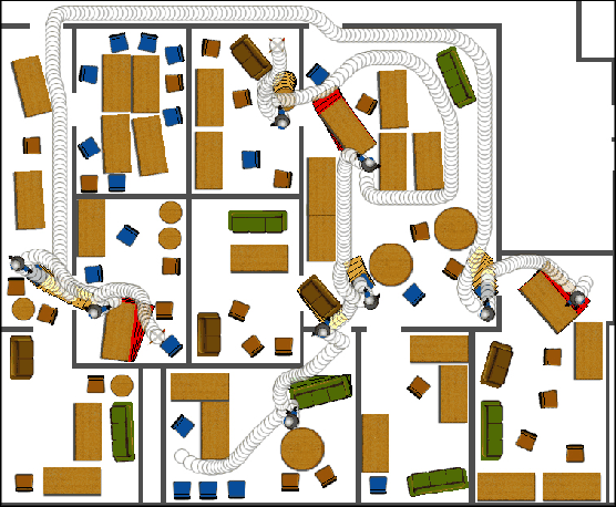
Figure 7.18:
This manipulation planning example was
solved in [915] and involves 90 movable pieces of furniture.
Some of them must be dragged out of the way to solve the problem.
Paths for two different queries are shown.
 |
Steven M LaValle
2012-04-20

![]() [16,17]. Let a
connected component of
[16,17]. Let a
connected component of ![]() refer to any connected component
of
refer to any connected component
of
![]() that is lifted into the state space by ignoring the mode.
There are two copies of the connected component of
that is lifted into the state space by ignoring the mode.
There are two copies of the connected component of
![]() , one for
each mode. For each connected component of
, one for
each mode. For each connected component of ![]() , a vertex exists
in
, a vertex exists
in
![]() . An edge is defined for each transfer path or transit
path that connects two connected components of
. An edge is defined for each transfer path or transit
path that connects two connected components of ![]() . The general
approach to manipulation planning then is as follows:
. The general
approach to manipulation planning then is as follows:

