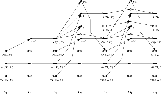
During the construction of the planning graph, information about the
conflict between operators and literals within a layer is maintained.
A conflict is called a mutex condition, which means that a pair
of literals2.4 or pair of operators is
mutually exclusive. Both cannot be chosen simultaneously without
leading to some kind of conflict. A pair in conflict is called mutex. For each layer, a mutex relation is defined that
indicates which pairs satisfy the mutex condition. A pair,
 , of operators is defined to be mutex if any of these
conditions is met:
Example 2..8 (The Planning Graph for the Flashlight)
Figure
2.20 shows the planning graph for Example
2.6. In the first layer,

expresses the initial
state. The only applicable operator is

. The operator
layer

contains

and three trivial operators, which
are needed to maintain the literals from

. The appearance of

enables the battery-insertion operator to
apply. Since variables are not allowed in operator definitions in a
planning graph, two different operators (labeled as

and

)
appear, one for each battery. Notice the edges drawn to

and

from their preconditions. The cap may also be replaced; hence,

is included in

. At the

layer, all possible
literals have been obtained. At

, all possible operators,
including the trivial ones, are included. Finally,

, and

will be the same as

. This implies that the planning graph
has stabilized.


![]() , of operators is defined to be mutex if any of these
conditions is met:
, of operators is defined to be mutex if any of these
conditions is met:
