Next: 3D triangles Up: 3.1.3 Other Models Previous: 3.1.3 Other Models
The method in Section 3.1.1 required nonconvex polygons
to be represented as a union of convex polygons. Instead, a boundary
representation of a nonconvex polygon may be directly encoded by
listing vertices in a specific order; assume that counterclockwise
order is used. Each polygon of ![]() vertices may be encoded by a list
of the form
vertices may be encoded by a list
of the form ![]() ,
, ![]() ,
, ![]() ,
, ![]() . It is
assumed that there is an edge between each
. It is
assumed that there is an edge between each ![]() and
and
![]() for each
for each ![]() from
from ![]() to
to ![]() , and also an edge
between
, and also an edge
between ![]() and
and ![]() . Ordinarily, the vertices should
be chosen in a way that makes the polygon simple, meaning that no edges intersect. In this case, there is a
well-defined interior of the polygon, which is to the left of every
edge, if the vertices are listed in counterclockwise order.
. Ordinarily, the vertices should
be chosen in a way that makes the polygon simple, meaning that no edges intersect. In this case, there is a
well-defined interior of the polygon, which is to the left of every
edge, if the vertices are listed in counterclockwise order.
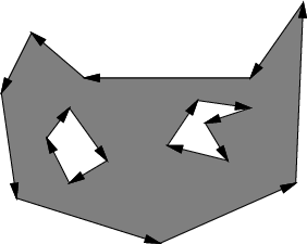
What if a polygon has a hole in it? In this case, the boundary of the hole can be expressed as a polygon, but with its vertices appearing in the clockwise direction. To the left of each edge is the interior of the outer polygon, and to the right is the hole, as shown in Figure 3.5
 |
Although the data structures are a little more complicated for three dimensions, boundary representations of nonconvex polyhedra may be expressed in a similar manner. In this case, instead of an edge list, one must specify faces, edges, and vertices, with pointers that indicate their incidence relations. Consistent orientations must also be chosen, and holes may be modeled once again by selecting opposite orientations.
Steven M LaValle 2012-04-20